<< radio home
<< index
by disinfoniacs #69 & #1
>>>>
T6 covered things such as volts, amps and ohms, but how do you measure them? Let’s look at the electronics tools that will help you measure voltage, current, resistance, power and more.
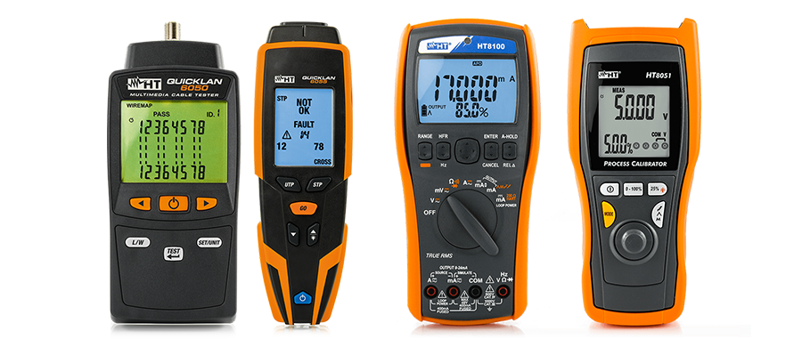
The most common tool is a multimeter, which measures voltage and resistance. Most multimeters come with a digital display, but analog versions are also available. When you want to measure a particular electrical property, you need to set the multimeter to the corresponding mode. For example, to measure DC voltage, you need to set the multimeter to the DC voltage mode, and for AC voltage, you need to set the multimeter to AC voltage mode.
Before taking any measurements with the multimeter, you should always make sure that the multimeter is set to the correct mode and range. Using the wrong mode or range could damage the multimeter or give incorrect readings. It's also important to ensure that the probes are connected correctly to the circuit, with the red probe connected to the positive terminal and the black probe connected to the negative terminal.
When measuring voltage or current, it's important to choose the appropriate range to get an accurate reading. If the range is set too low, the multimeter may not be able to measure the full voltage or current, and if it's set too high, the reading may be inaccurate.
Ohms is a unit of measurement for electrical resistance. Resistance refers to the opposition to the flow of electric current in a material or a device. An ohmmeter is a device that measures the resistance of a component or circuit. When measuring circuit resistance with an ohmmeter, it is essential to ensure that the circuit is not powered. Otherwise, the meter will give inaccurate readings and could potentially damage the device being measured. It is also important to select the appropriate range on the ohmmeter to obtain accurate measurements.
Here’s a helpful troubleshooting tip for measuring resistance: If you notice an increase in resistance over time, it could indicate that the ohmmeter is connected across a large, discharged capacitor. This is because the measurement process involves charging up the capacitor. To avoid this issue, you can discharge the capacitor before taking resistance measurements.
In addition to the ohmmeter, the multimeter also includes a voltmeter, which is used to measure the electric potential or electromotive force of a circuit. The basic unit of voltage is called the volt, which is why the device is called a voltmeter.
When measuring voltage, it is important to connect the voltmeter in parallel with the circuit. This means that the voltmeter is positioned across the voltage that is being measured. It is important not to attempt to measure voltage using the resistance setting on your meter, as this could potentially damage the multimeter.
Some multimeters come equipped with an ammeter, a device that is used to measure the flow of electric current in a circuit (measured in amps, hence the name). When measuring current with an ammeter, it's essential to remember that the meter must be connected in series with the component being tested. This means that the current must flow through the ammeter to provide an accurate measurement.
It's crucial to select the correct range on the ammeter to avoid damaging the meter and ensure accurate readings. It's also important to be careful when measuring current, as excessive current can cause the device being tested to overheat and fail. In some cases, it may be necessary to use a clamp meter to measure current without interrupting the circuit.
An antenna analyzer is an essential tool for any radio operator, allowing them to determine whether the antenna is operating at its maximum efficiency. The analyzer is used to measure the impedance of an antenna, which is the measure of the opposition to the flow of an alternating current. This impedance is represented as a complex number with both magnitude and phase, and an antenna analyzer can measure this impedance at various frequencies.
Antenna analyzers typically work by sending out a test signal at different frequencies and measuring the resulting current and voltage. By comparing the current and voltage measurements at each frequency, the analyzer can calculate the antenna's impedance. The analyzer can also plot this data on a graph to show the frequency response of the antenna, allowing the operator to see the resonant frequency and the bandwidth of the antenna. This information is critical in optimizing the antenna's performance for a specific operating frequency or range of frequencies.
Some antenna analyzers also include a built-in antenna tuner, which can adjust the antenna's impedance to match the desired frequency. This can improve the antenna's efficiency and reduce the amount of signal loss or interference. Antenna analyzers are used not only by amateur radio operators but also by professionals in the telecommunications industry to optimize their antenna systems.
When testing radio or other equipment, it's essential to follow good practice guidelines and not transmit over the air, as this could cause interference with other devices or signals. To avoid this, a tool called a dummy load is often used during testing to prevent transmitting signals over the air. A dummy load is essentially a non-inductive resistor mounted on a heat sink that simulates an antenna.
Replacing the antenna with a dummy load allows the user to test the equipment for as long as necessary, based on the dummy load's rating, without the risk of interference. Using a dummy load is particularly useful when testing radio transmitters, as it allows the transmitter to be tested without actually transmitting a signal over the airwaves, which could cause unwanted interference or violate regulations.
<< previous lesson | next lesson >>
---
<< radio home
<< index