<< radio home
<< index
by disinfoniacs #69 & #1
>>>>
A schematic diagram is an electrical drawing that uses standard symbols to represent components in a circuit. It's like a roadmap of a circuit that shows how components are connected.
On the technician exam, you may be asked to identify an element in a schematic diagram. There are three possible schematics you'll see, and knowing the symbols for common components will help you identify them.
Some of the most common symbols you'll see in a schematic diagram include a resistor (fixed value) and a variable resistor (adjustable value). Whenever you see an arrow pointing to the middle of the symbol, it's the variable version of that component. Other symbols include capacitor, transistor, switch (single pole-single throw), battery, LED, transformer, variable inductor, antenna, and lamp/bulb.
By combining multiple components from the list and adding a few additional components, you can make more complex circuits. For example, a transformer is a frequently used component that is commonly used to change one AC voltage to another. In ham radio, a transformer can be used to change 120-volt AC house current to a lower AC voltage.
However, if you need to go from AC current to DC current, a transformer alone won't work. In this case, you can use a rectifier to convert alternating current into a varying direct current signal. When you see transformers and rectifiers together, you usually also see a regulator circuit that controls voltage from a power supply.
<< previous lesson | next lesson >>
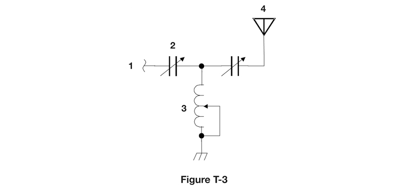
The following are the schematics you may see on the exam. I've taken the liberty of labeling them below.


<< previous lesson | next lesson >>
---
<< radio home
<< index